Drawings
Measurements are in millimetres. Numbers in circles match the notes under each drawing. On a phone, tap "Open full size" and pinch to zoom.
- Slab 3,260 × 2,960. Inside face of the formwork on the string lines.
- Profiles about 1 m outside each corner (or as room allows). Strings mark the slab edge. Diagonals must match at 4,403.
- Doors on the front edge. Face them north to north-east if you can: winter sun in, no hot western glare.
Gear shown dashed. Doors open outward to keep the floor clear. The bar has 428 to each side wall, enough to load plates.
- Trimdek 0.42 Colorbond on a foil roof blanket, screwed to the battens.
- Battens 70 × 35 H3, laid flat, about 822 apart.
- Rafters 140 × 45 MGP10 at 600 centres.
- R2.5 batts above a 9 mm ply ceiling fixed to the rafters.
- Fascia 140 × 45 H3 with 115 quad gutter.
- 12 mm structural ply lining with R2.0 wall batts behind.
- Slab 100 thick, SL82 mesh 30 below the surface.
- Edge beam 300 wide × 400 deep with 3-L11TM trench mesh.
- 20 mm Class 3 crushed rock, 100 compacted, under 200 µm film.
- Natural ground. FFL is 100 above it.
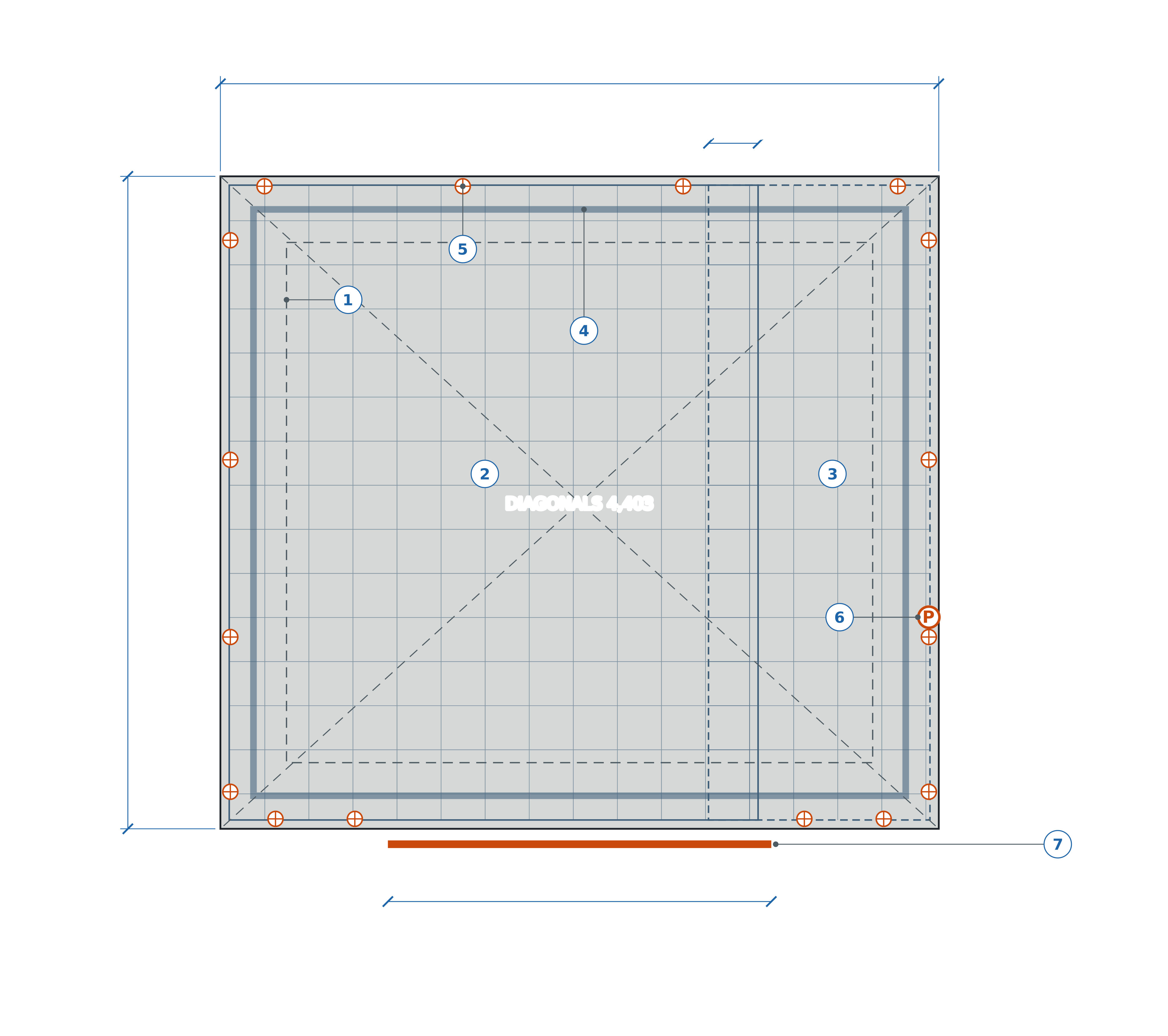
- Edge beam, 300 wide around the perimeter (dashed line is its inside edge).
- Mesh piece A: SL82, 2,880 × 2,400.
- Mesh piece B: SL82, 2,880 × 1,005, lapped 225 over A. Both come from one 6.0 × 2.4 m sheet.
- Trench mesh 3-L11TM on 50 mm chairs, lapped 500 at the corners.
- Anchor screws, M12 × 125, through the bottom plates: 16 in all. Positions are in the table below.
- Power conduit, suggested spot under the right-hand window. Agree it with your electrician before the pour.
- Door opening. The bottom plate runs through here until the frame is anchored, then gets cut out.
| Wall | Positions | Measured |
|---|---|---|
| Back wall | 200, 1,100, 2,100, 3,074 | from the left end |
| Front wall | 250, 610, 2,650, 3,010 | from the left end, either side of the doorway |
| Each side wall | 290, 1,286, 2,090, 2,792 | from the back face of the building |
Each anchor sits on the wall's centre line, 45 in from the slab edge, between studs.
- Colorbond Custom Orb cladding over wall wrap.
- Cladding laps 25 below the slab top so rain drips clear.
- Formwork 150 × 38 on edge, pegs at 900. Top of the board is the slab top.
- Stud 90 × 45 MGP10 H2.
- 12 mm ply lining, kept 20 off the slab.
- Bottom plate 90 × 45 H3 on a DPC strip.
- M12 × 125 anchor screw, about 80 into the concrete.
- SL82 mesh on 50 chairs, 30 below the surface.
- 200 µm film under everything, laps 200 and taped.
- 20 mm Class 3 crushed rock, compacted in two layers.
- 3-L11TM trench mesh on 50 chairs, 50 off the bottom.
- Bottom plate 90 × 45 H3, on DPC, anchored per S01.
- Double top plate, 90 × 45, full length.
- Three-stud corners, so the lining has something to fix to.
- Studs at 600 centres measured from the left-hand end.
- Noggings at 1,200 and 2,400 (centres). The 2,400 row catches the lining joint.
- X strap brace on the outside face, tensioned, nailed to every stud it crosses.
- Bottom plate 90 × 45 H3. Leave it running through the doorway until the frame is anchored, then cut it out.
- Double top plate, 90 × 45, full length.
- Three-stud corners.
- Door jamb studs, full height.
- Jack studs carry the lintel.
- Lintel: two 190 × 45 nailed together, tight under the top plate.
- Head trimmer laid flat under the lintel. Change its height to suit your door frame.
- Nogging at 1,200. Above 2,400 the top plate catches the lining.
- Bottom plate 90 × 45 H3, on DPC.
- Double raked top plate, 90 × 45, cut 3° at both ends. Its slope matches the rafters.
- End studs. Long points: 2,515 at the back, 2,372 at the front.
- Studs at 600 centres measured from the back face of the building (so they line up with the ply joints).
- Window jamb studs, full height.
- Jack studs, 2,055.
- Window lintel: two 140 × 45 nailed together, 1,320 long.
- Sill trimmer, laid flat.
- Cripples under the sill and over the lintel.
- Noggings at 1,200 and 2,400 (2,400 only where there's room under the top plate).
- Rafters 140 × 45 MGP10 H2, 3,365 long, plumb cut both ends. Flush with the back of the frame, 400 past the front.
- End rafters sit flush with the outside of each side wall.
- Battens 70 × 35 H3, laid flat, 3,410 long, 75 past each side wall.
- Blocking, 140 × 45, between the rafters over the back and front walls.
- Fascia 140 × 45 H3 across the rafter ends.
- 115 quad gutter, outlet and downpipe at the right-hand end, to a tank or the garden.
- Ceiling joint noggings, laid flat, 2,400 in from the back wall's inside face.
- Wall frames below, shown dashed.